Electrical


I checked the current draw of the truck’s system with my clamp meter around both ground cables. There were like 8 wires on the positive terminal so that was not going to fit. I saw current draw of 140-150 amps!! It’s only a 120 amp alternator!! I didn’t have my schematics with me so I took my ohm meter and probed about to see how the large grid relays were wired. Both hots went straight to the positive battery terminal. It was a bit rigged by the previous owner. So I disconnected both large grid heater leads. The current draw was now between 35-50 amps now. Sweet!!

Here is a Ford type relay mounted between the grid relays and the battery. It looks after market and rigged at that. A couple of it’s wires went to the positive terminal bolt too.

Here are all of the wires stuck onto the positive terminal bolt! The 2 black leads are the fusible links for the 2 grid heaters. The other 2 leads are from the after market looking Ford relay.

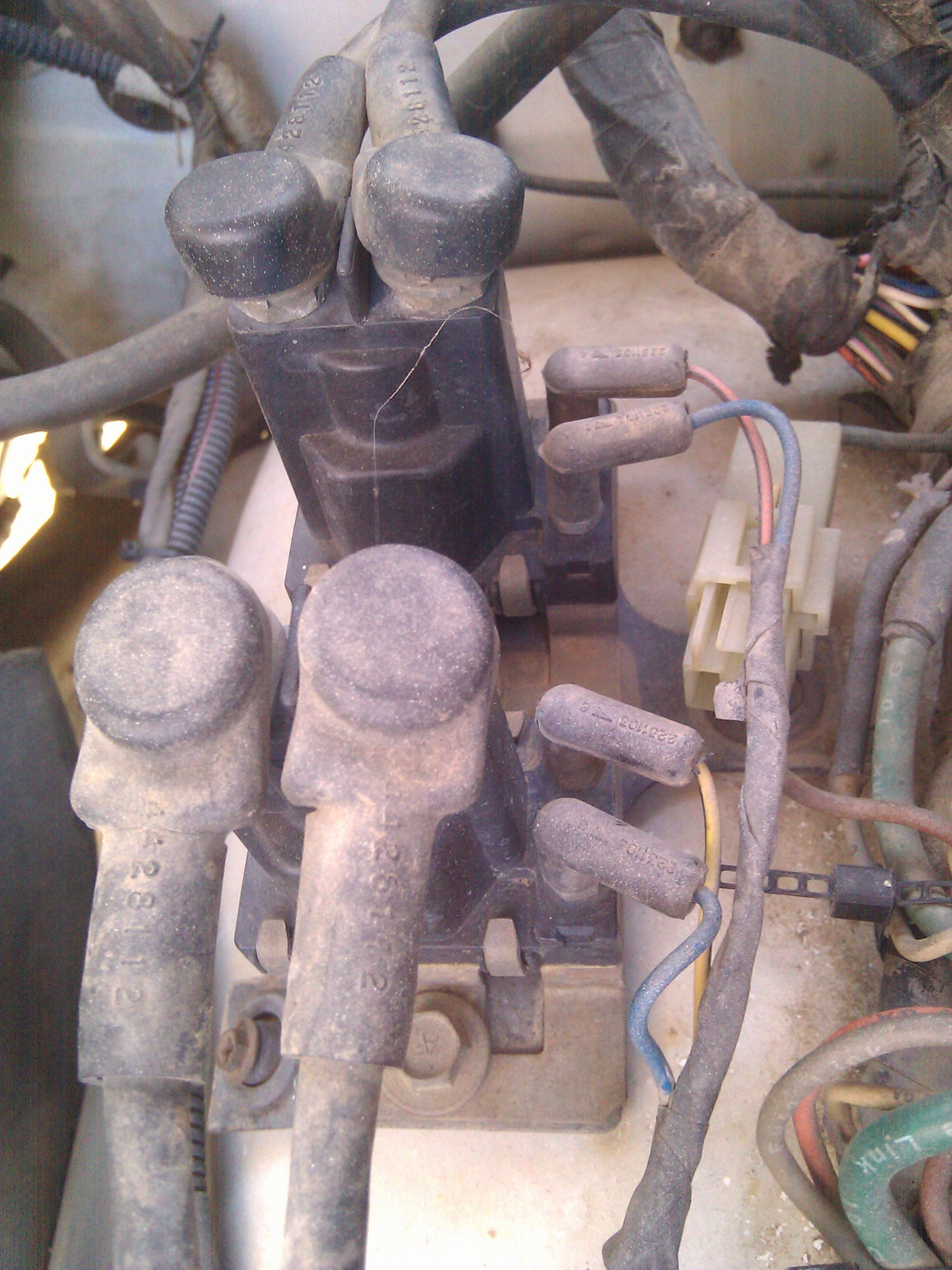
Here are the grid relays. One for each of the 2 grid heaters. The main posts were not shorted together as I checked with an ohm meter. Still need to look at more things to see why the current is dropping the alternator voltage down so low.
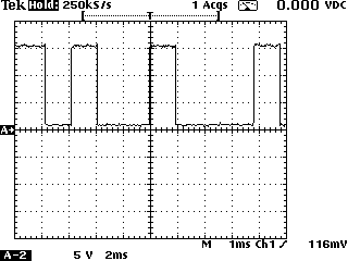
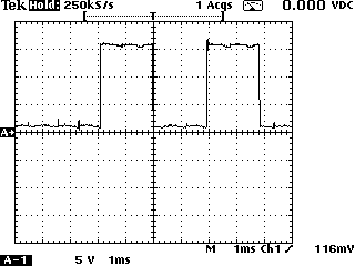
So now I wanted to see how the field terminal looked on a scope. These pics below are the 2 scope shots I took looking at the upper field terminal while charging. Sure enough there are waveforms present!! It shows the pcm has proper output. I could not get a sync on the waveforms, but at least I got good enough shots to show what a proper pcm output is suppose to look like. The crispness of the waveforms told me the pcm field control was working fine.
This afternoon I tried to see if I could make the alternator charge by shorting the top field terminal to ground with a 5.6 ohm resistor. I placed a dvm on the battery and started the Dodge. It was not charging. Shorting the top field terminal to ground with the resistor did not make the dvm show a higher voltage. I tried a few more times. I even tried using a piece of wire. No change. After the last attempt the alternator started charging. But I don’t think it was due to me. I think it’s still intermittent. The one odd thing I noticed during these attempts is that the alternator got warm fast. Very warm for not charging and for only running for a minute or so. It occurred to me that it’s possible that the alternator is charging, but that the load is far too high and it just sags. Or maybe the diodes are weak and it sags. I also removed the wiring to the grid relays to kill any load but they didn’t clunk or anything, so I think they were not engaged. The next attempt I’ll bring my current clamp meter and see how much current is actually flowing. A warm alternator means current is flowing!

This afternoon, we took the truck for a drive. The alternator was intermittent. But the second try to start it worked fine. So we took a 25 mile drive.

Since this alternator has a relay between it and the 12v battery, and the ecm for the truck controlling the ground connection, then a test could be devised that would duplicate either end. For the relay, it could be pulled from it’s socket and a jumper placed across the output terminals. Then I could vary the ecm by just disconnecting it and using some value of resistor to control the current to the field. I’m fairly sure the ecm might be using pwm for controlling how grounded that side of the field gets. It’s works like an electric motor controller. In this testing maybe I will be able to better understand how to devise a stress test for the ecm signal that is controlling the field of the alternator. Maybe a simple resistor to ground with current measurement. Since the field current should be around a few amps worst case, this test holds some merit.

« Previous PageNext Page »