I left the alternator in the truck, but I removed the brush assembly from it anyway. I read that a guy in one of the forums thought he could do it this way after taking it out to repair it.
Remove the negative battery cable first!!! You can see several nuts that need to be removed. You will need 6mm, 7, 8mm, 10mm, 3/8″ sockets. Also a 12mm deep socket is needed. It’s very easy to loose these nuts!!!!!

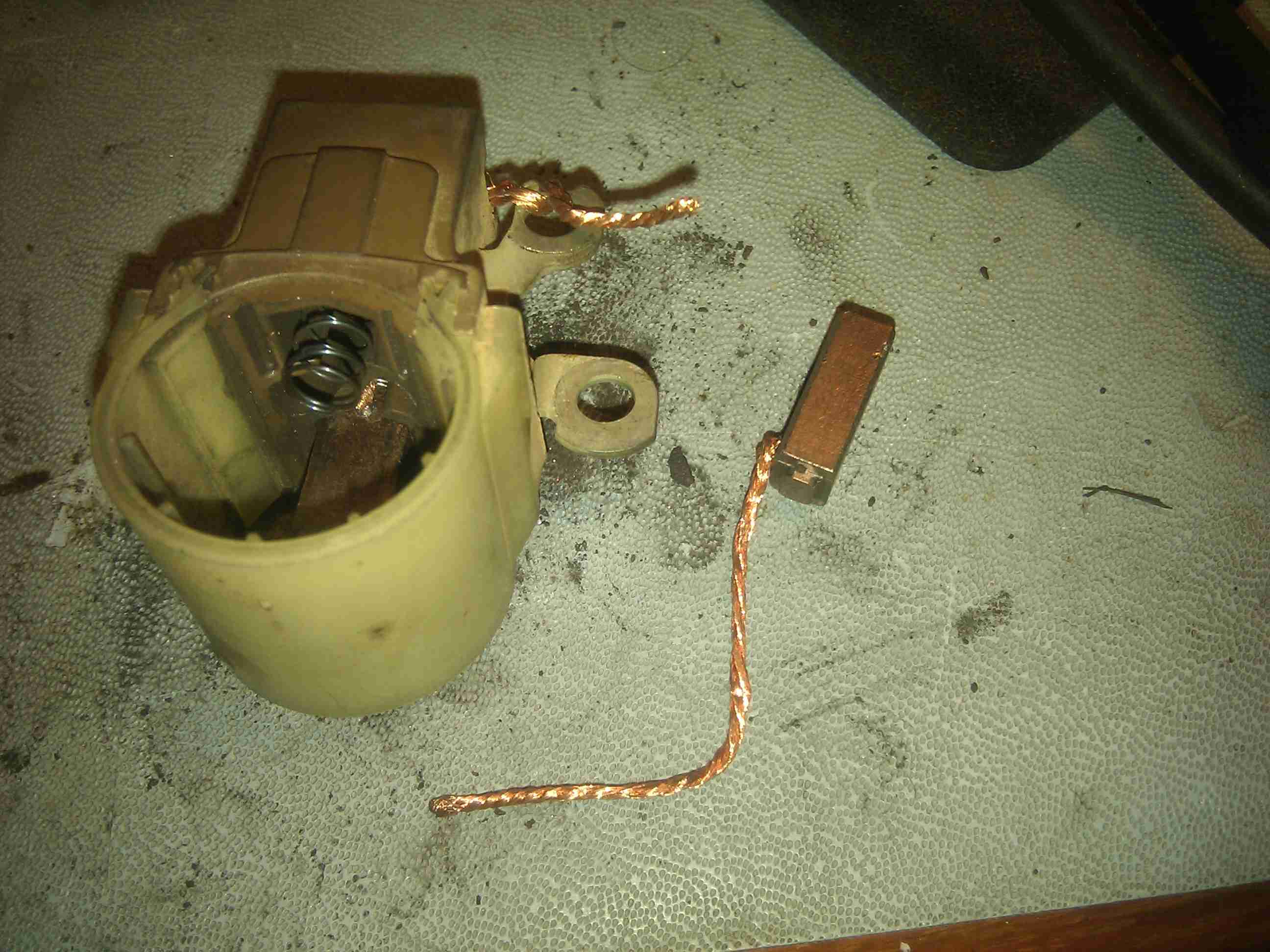
Don’t loose this ground tab when you take the cover off of the alternator!!!
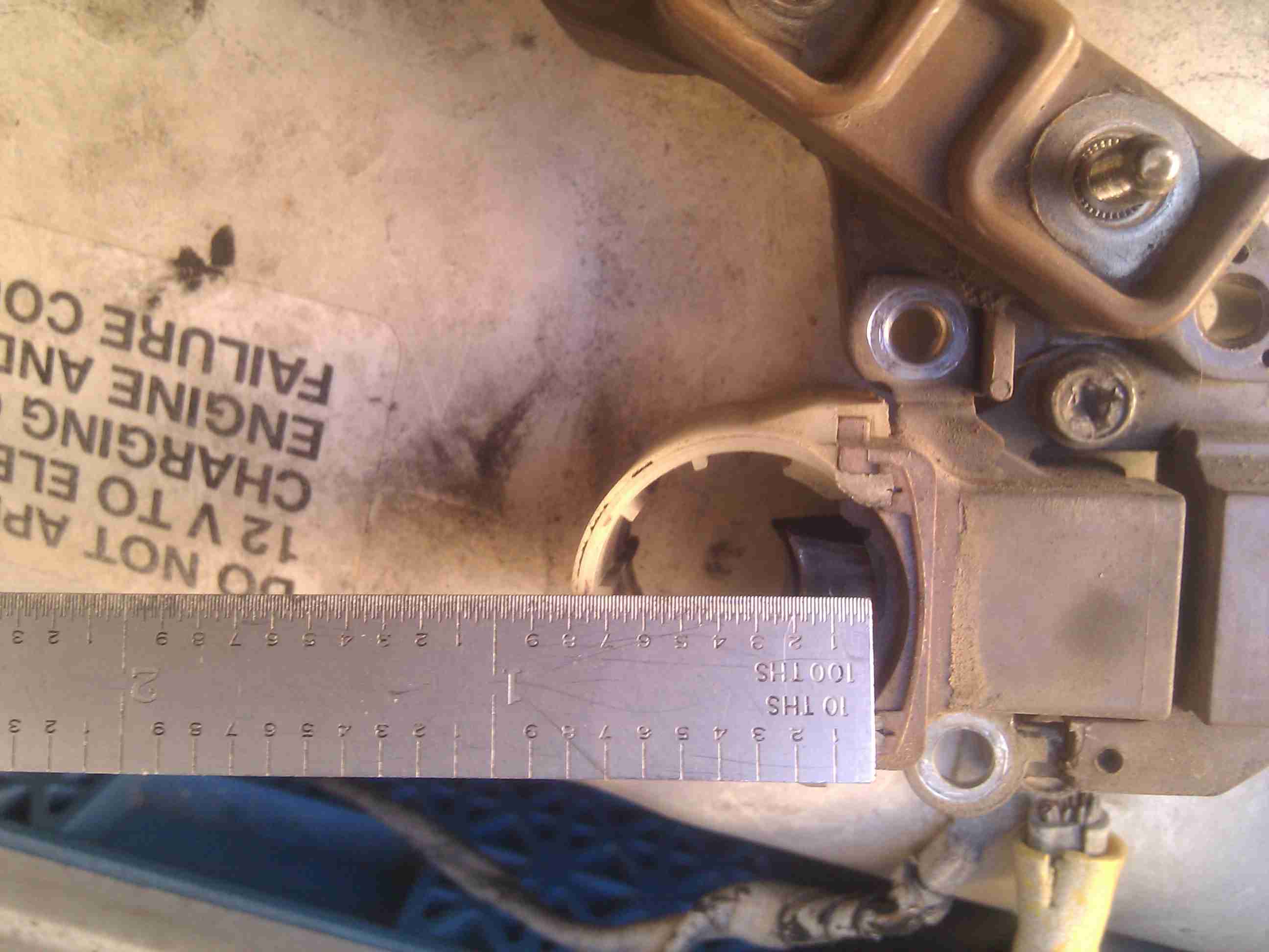
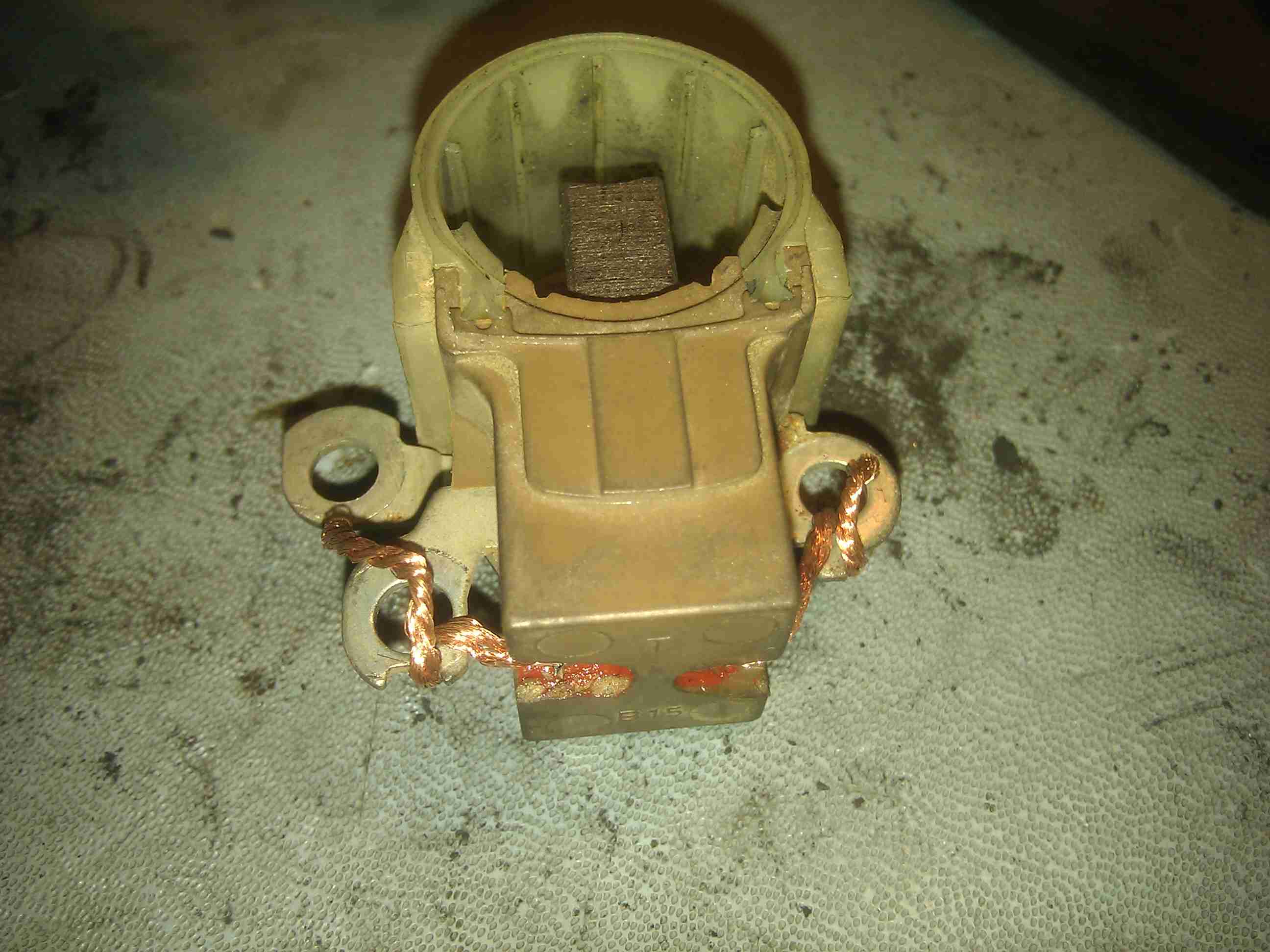
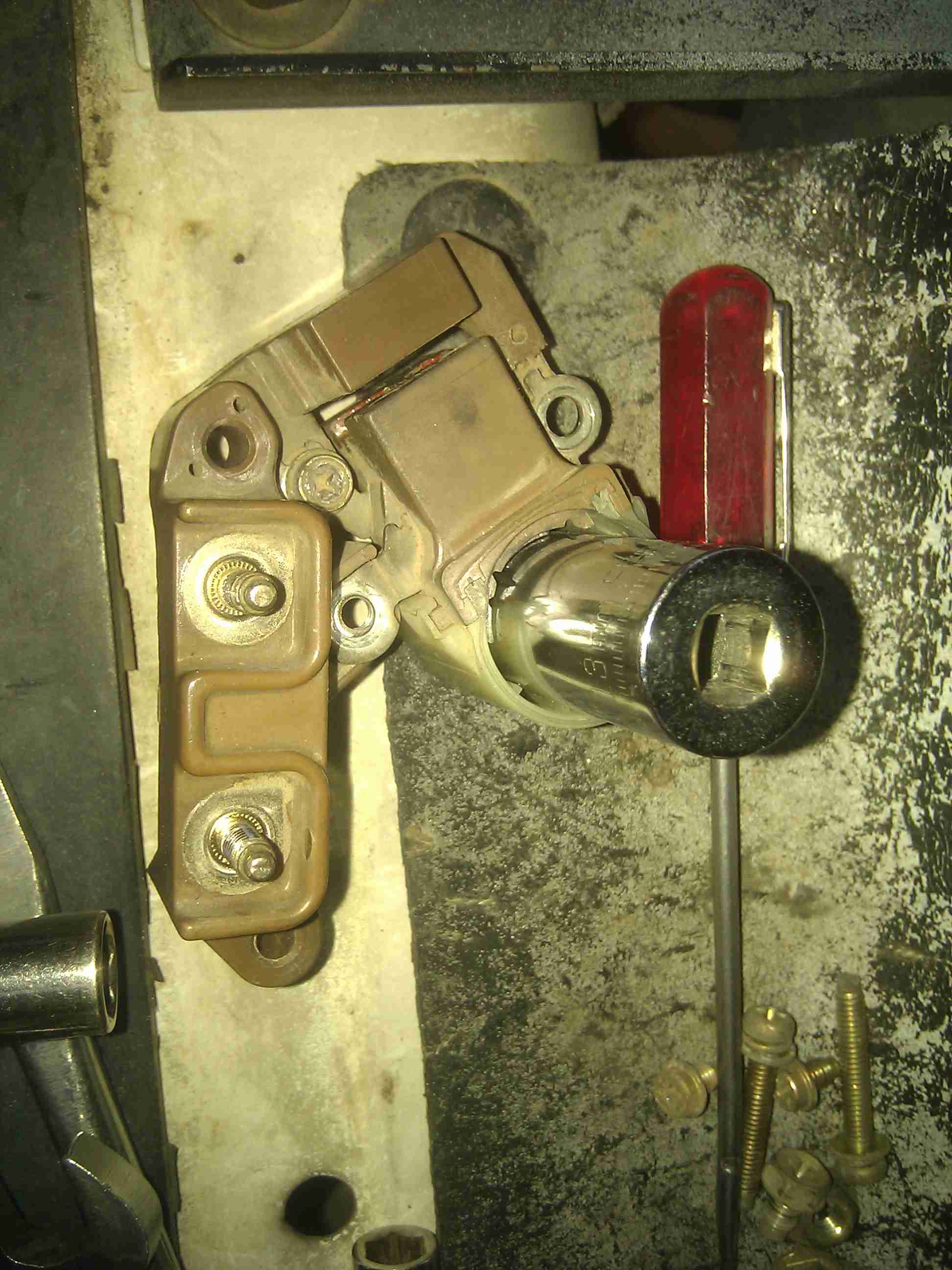
You can see that the top brush is worn more than the lower one. Not sure if this means much. The upper brush is sticking out about .200″. I left the other part attached as it was tough to get to some of the phillips head screws. Their heads are phillips only and soft at that. They don’t have the standard 6mm or 1/4″ hex that so many do. If it gets stripped, it spells trouble. You can see mine is dinged up already from my attempts to get it apart.
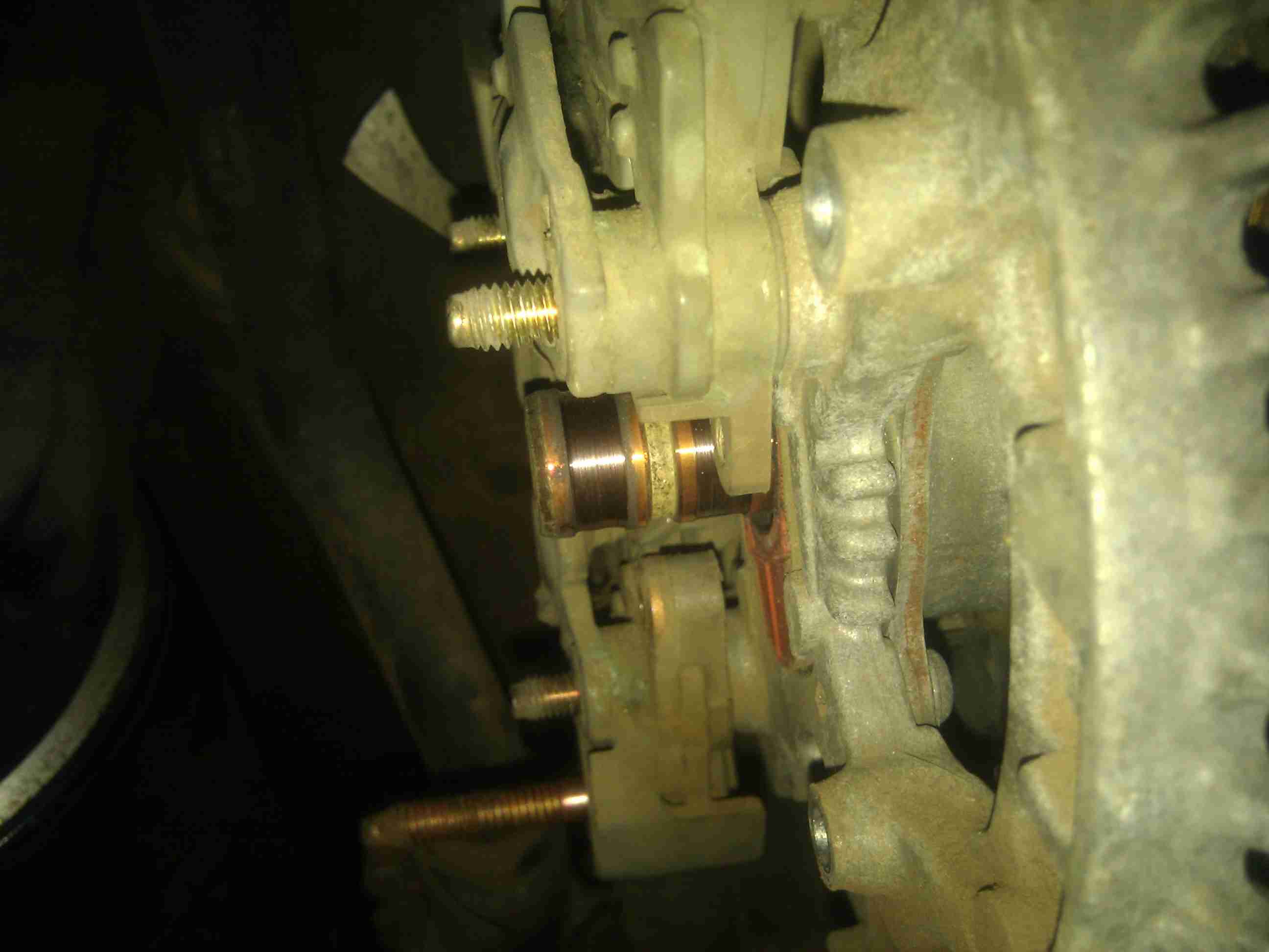
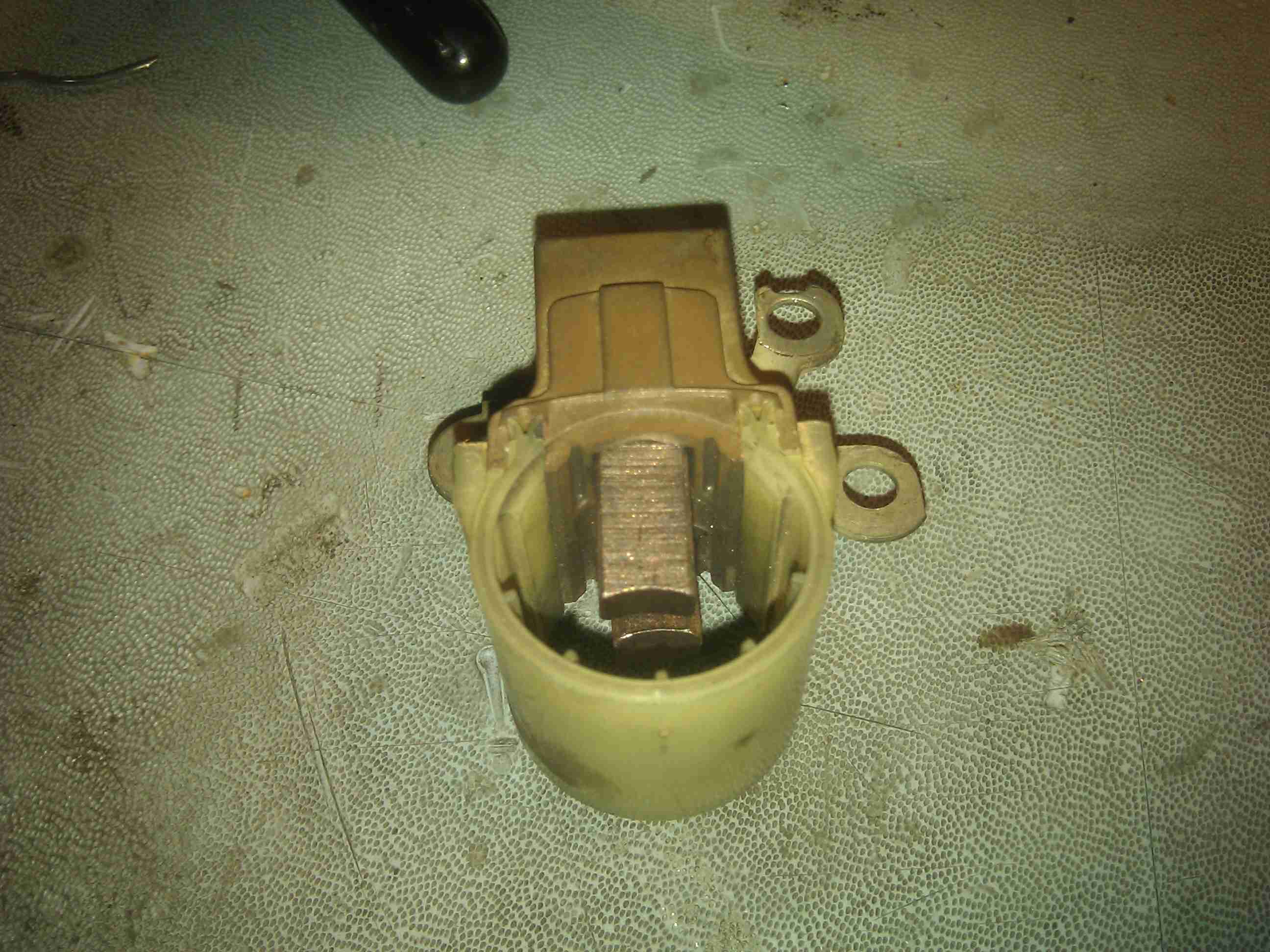
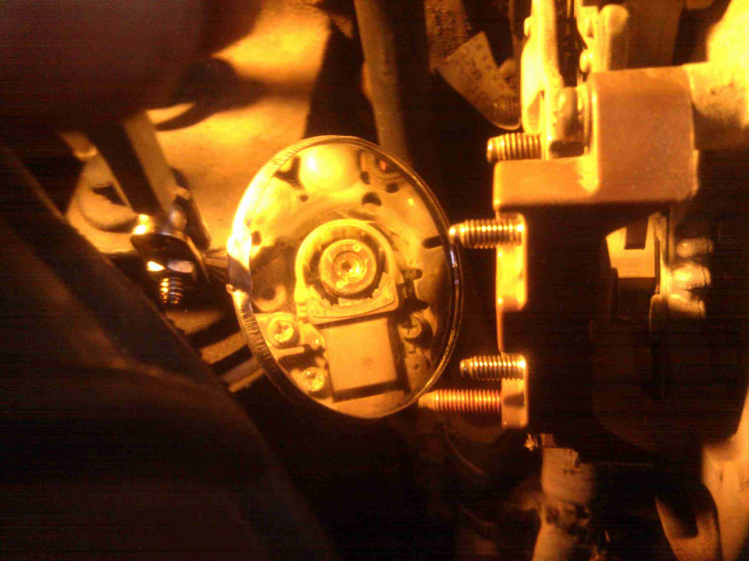
Here you can see wear on the 2 slip rings. I’d guess it’s about .030″-.050″ deep. It just means that the brushes have to reach out further to make contact.
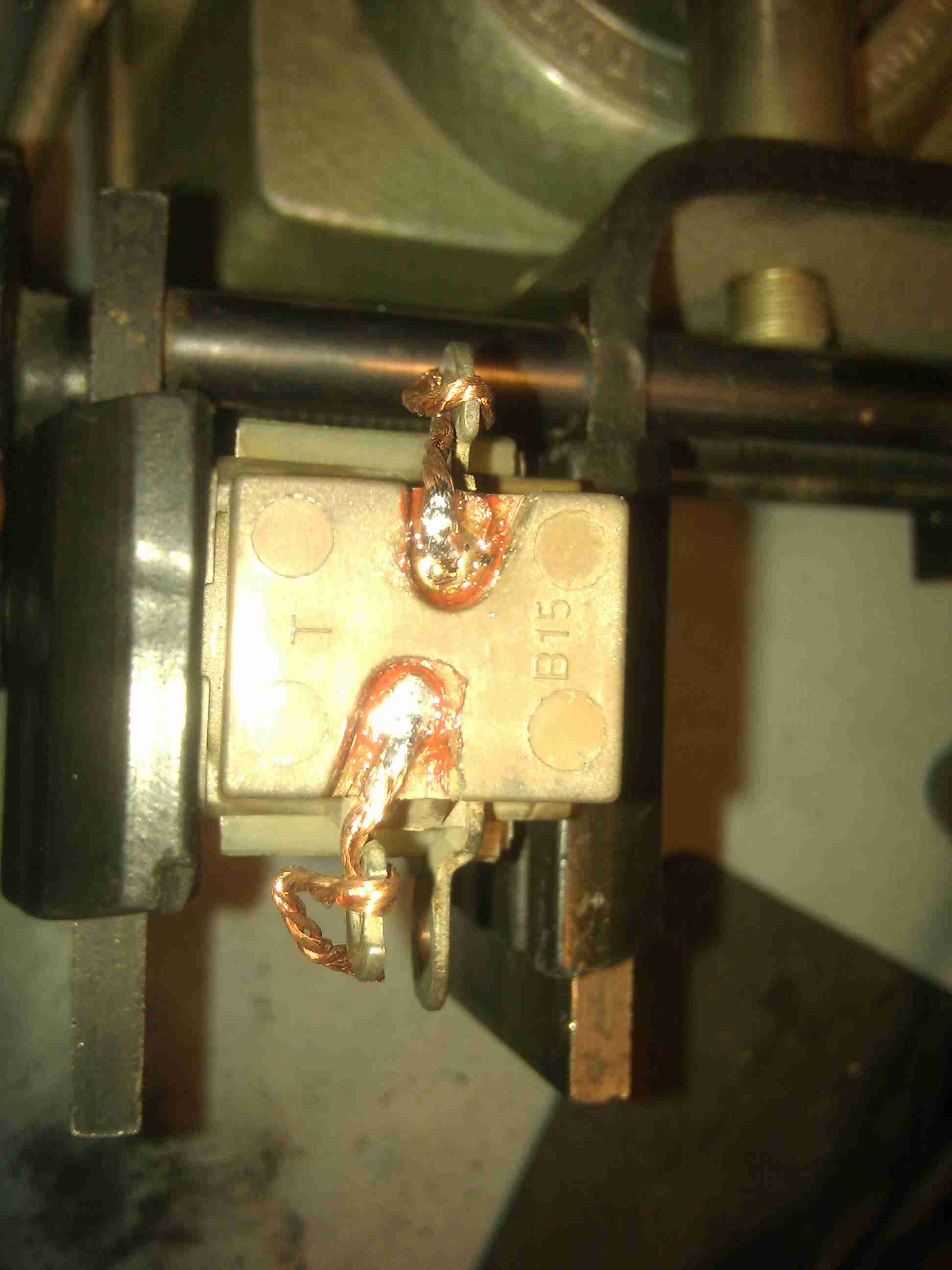
The solder joints for the brush leads are here, under the red hard coating. I scrapped it off with a #11 Exacto knife.
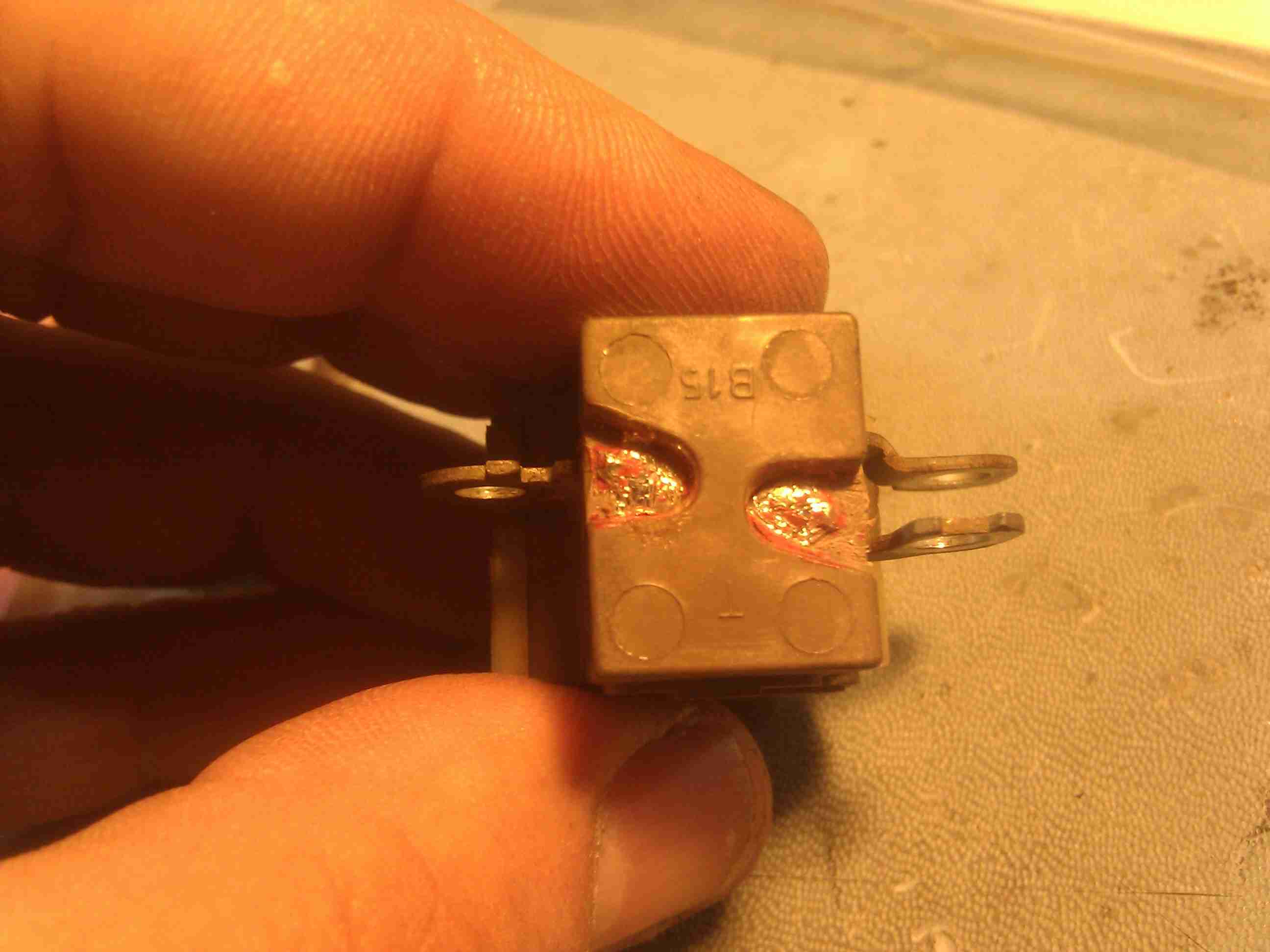
I heated up the solder joints and they eventually let the leads pull through due to the spring tension. So there is no need to pull on the carbon part of the brushes. You can see that these brushes look to have a lot of life left in them. Notice that the ones I got from the rebuild shop are radiussed already. One of the springs did not want to come out, so I left it in.
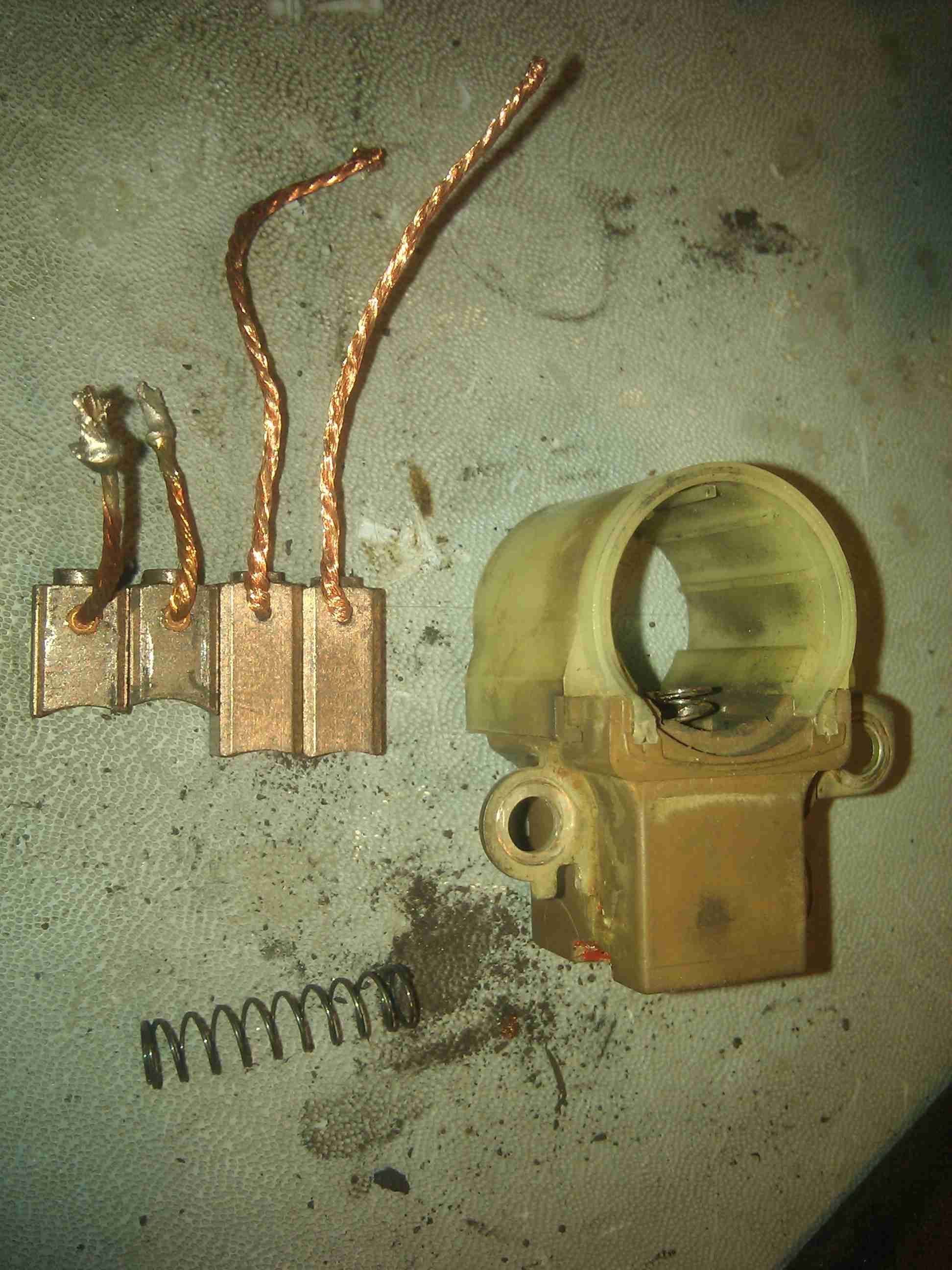
The square ends of the new brushes fit completely inside the springs.
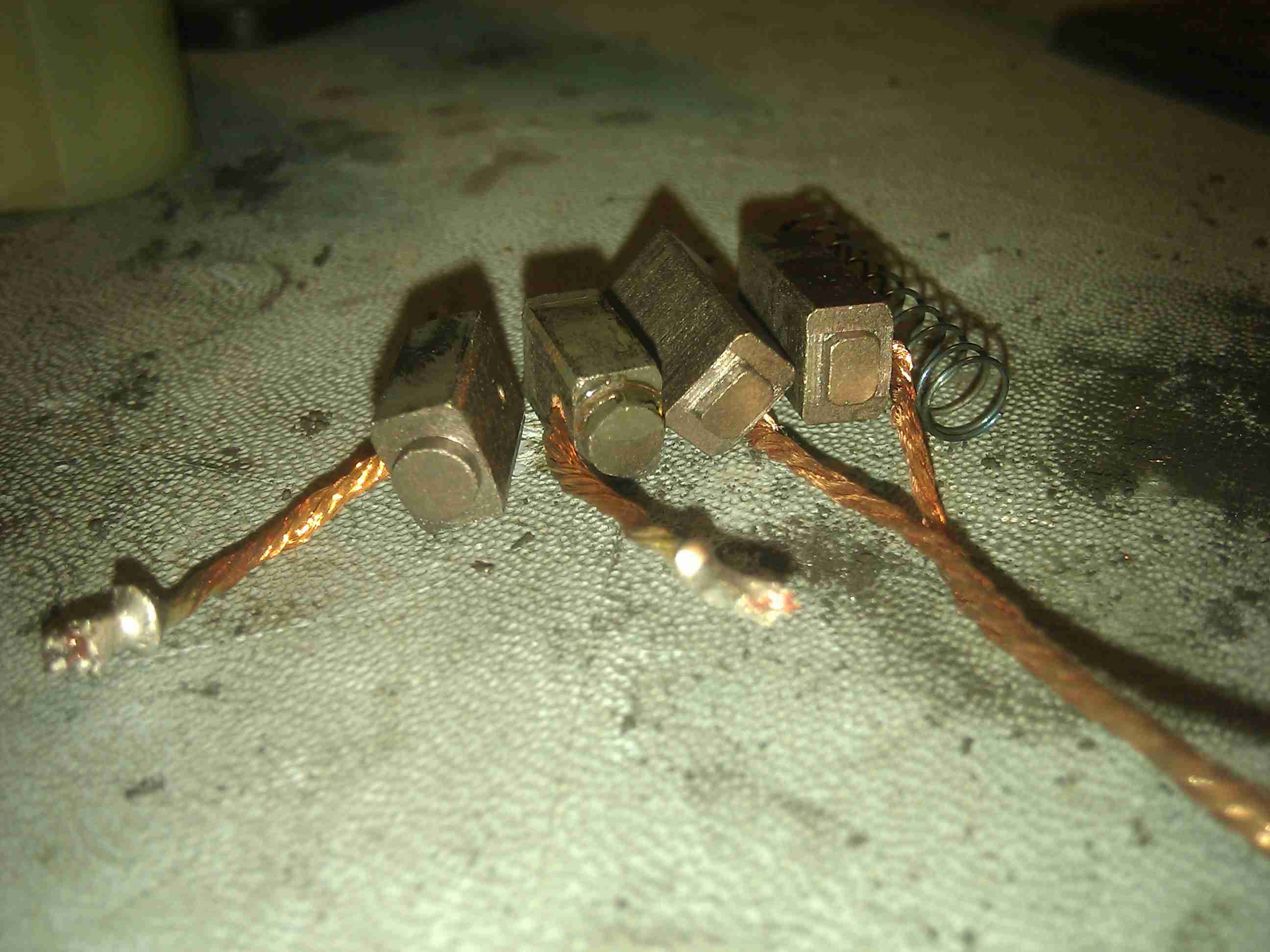
Each brush lead feeds through a passage under the actual brush. That round hole goes straight back to they get soldered.

Just bend the lead and feed the brush and brush lead into place like I did the first one.
Then wrap the lead around the ring lug to hold it in place when soldering. The spring tension will make it hard to hold in place any other way.
Make sure the brushes are sticking out as much as possible without drooping downward at all. Then solder them back in place.
These are about how far new ones will stick out. Mine drooped some as I was installing them onto the alternator. So I’d pull them in another .060″ or so.
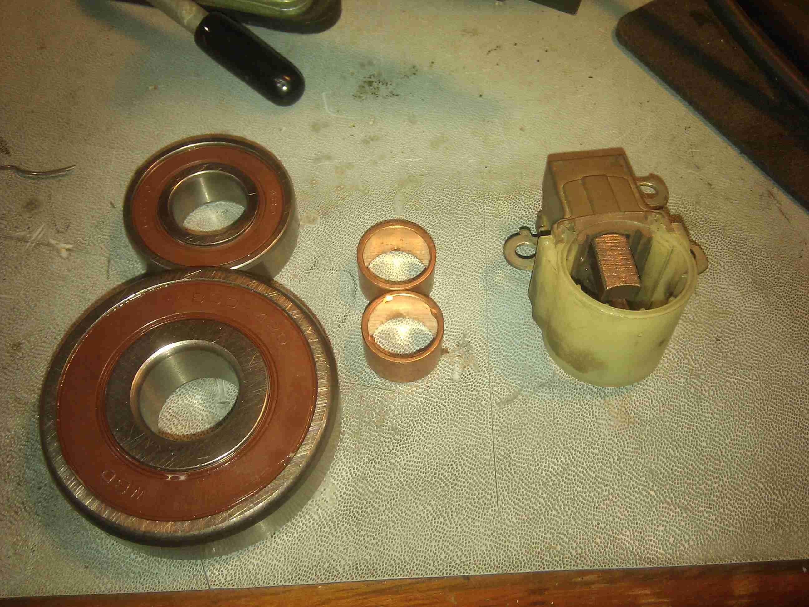
Here is the complete kit I got from the rebuild shop, except for the brush holder. It was not included, but this one is in fine shape. I won’t be doing the slip rings or bearings this time around as I’m just trying to debug the intermittent charging problem.
I screwed the terminal post assembly back to the brush holder. That screw needs to be tight and not come loose. Then I added a socket to hold the brushes in place during install back onto the slip rings.
You can see where the screws are reinstalled from the rear of the alternator.
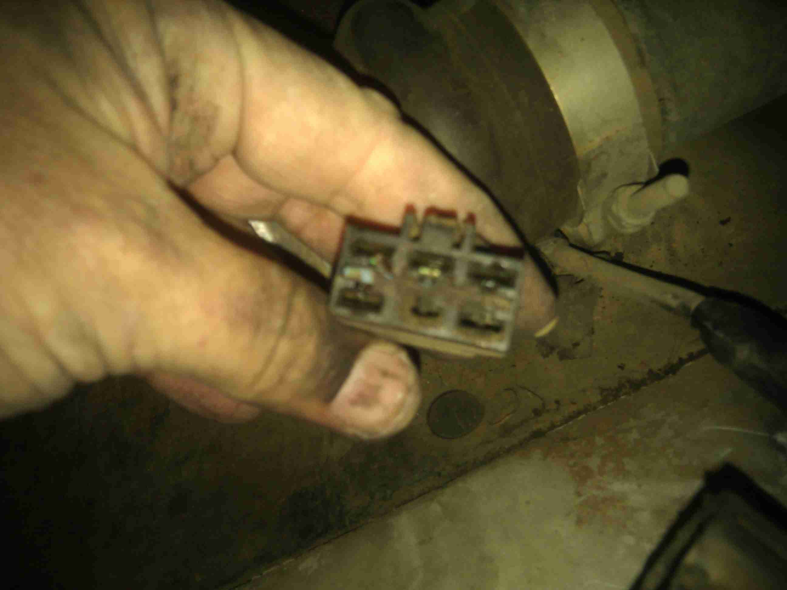
On the passenger inner fender I took apart the big black connector and inspected for corrosion. It was dirty with crud, but not corroded.
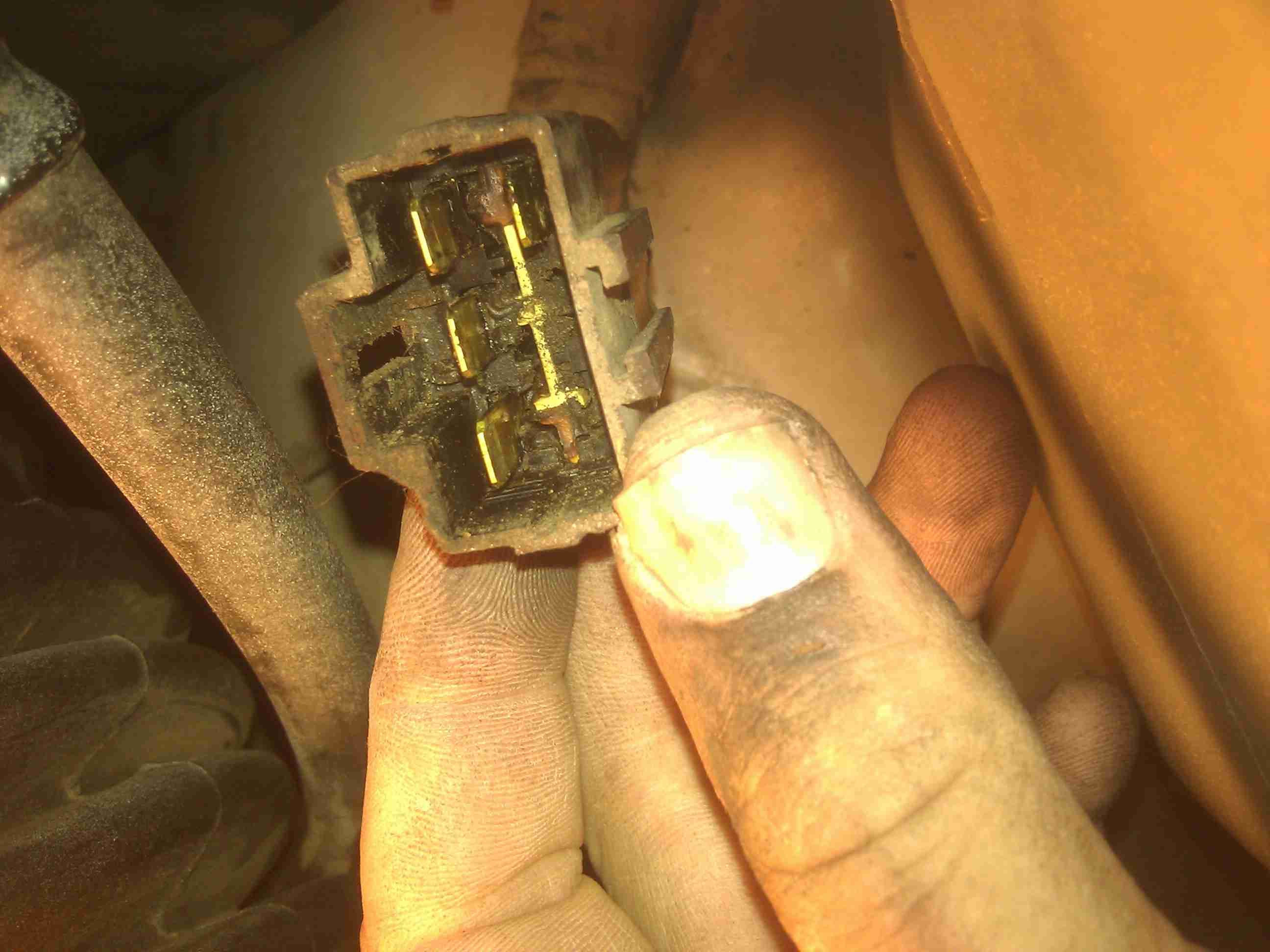
Here is it’s mate out of focus. Cruddy but not corroded. Cleaning both of these did nothing to help the intermittent alternator problem. Neither did replacing the brushes.