December 2011
Monthly Archive
Thu 22 Dec 2011
Posted by Administrator under
Alternator ,
ElectricalNo Comments
What a day yesterday was!! I load tested the alternator using the grid heaters. It seemed to really kill the alternator output. So I took the alternator to a rebuild shop I’ve used for 25 years, and they tested it on their fixture. At full field current it showed 22 volts and 120+ amps and climbing! Almost no ripple in the waveform either!! I was happy!! But then why were the grid heaters bogging it down so badly?? One other pain was that there was a squealing sound under the hood. I could not tell if it was the alternator or either of the idler pulleys. I had also taken the alternator to Kragen to have it tested. Their tester is lame. But the parts gal heard clearly that there was bearing noise. I heard it maybe one time. She looked at me like I was deaf. So with the alternator already out I tore it completely apart and put in new bearings. The pics of the alternator rebuild will be in another post. The new bearings did in fact take out the squealing completely!!!
I connected a dvm from the alternator output bolt to the positive battery terminal. It read .6v when one grid relay was powered. .6v x 80a = 48 watts of lost power. Also the large 6 ga wire over on the fender well has a large bullet connector on it that gets warm. That means it’s not doing it’s job perfectly. I took it apart and it was oxidized inside. Sometime I’ll either cut that connector out or try and clean it.
So after the alternator rebuild I went after the grid relays. Before the alternator was removed, I had turned the ignition on but left the engine off. Then I used jumpers to activate the grid relays manually. Each relay was sticking!!! Sometimes both of them would stick in the on position for 10 to 20 seconds at the same time!! Time for a tear down!! The tear down pics will also be in another post. I found the problem in each relay that caused the sticking. Once it was fixed, they would come on for 10 seconds then off. Then on again for 5 seconds. Then off. This was all pcm controlled. I tried to feel each relay to see if they were coming on at the same time. I don’t think they were! I think they were alternating. But the temperature warmed up and they stopped engaging before I could figure it out for sure. So I’ll do that tomorrow morning!!
Mon 19 Dec 2011
Posted by Administrator under
Alternator ,
ElectricalNo Comments
I checked the current draw of the truck’s system with my clamp meter around both ground cables. There were like 8 wires on the positive terminal so that was not going to fit. I saw current draw of 140-150 amps!! It’s only a 120 amp alternator!! I didn’t have my schematics with me so I took my ohm meter and probed about to see how the large grid relays were wired. Both hots went straight to the positive battery terminal. It was a bit rigged by the previous owner. So I disconnected both large grid heater leads. The current draw was now between 35-50 amps now. Sweet!!
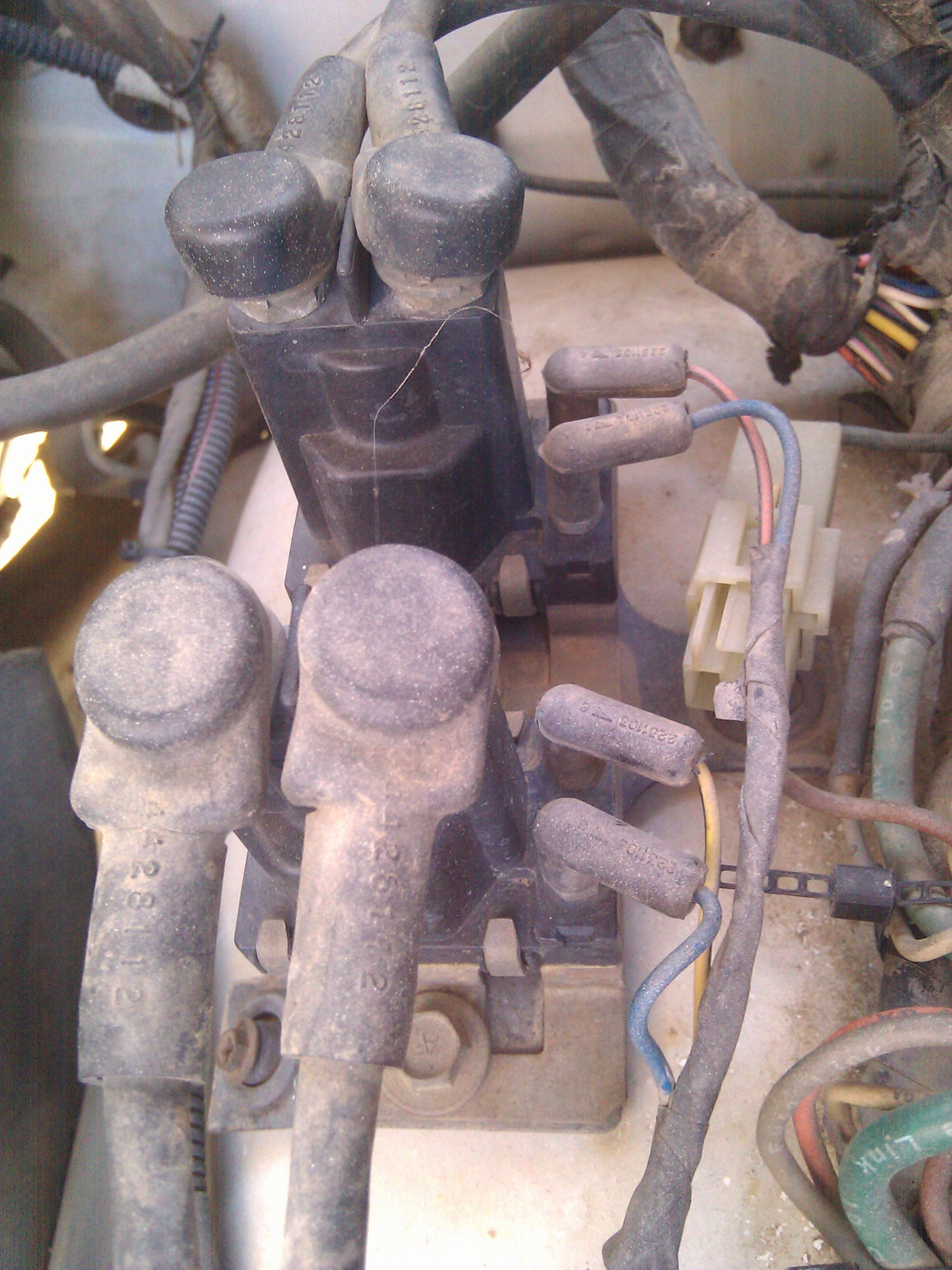
Here is a Ford type relay mounted between the grid relays and the battery. It looks after market and rigged at that. A couple of it’s wires went to the positive terminal bolt too.

Here are all of the wires stuck onto the positive terminal bolt! The 2 black leads are the fusible links for the 2 grid heaters. The other 2 leads are from the after market looking Ford relay.

Here are the grid relays. One for each of the 2 grid heaters. The main posts were not shorted together as I checked with an ohm meter. Still need to look at more things to see why the current is dropping the alternator voltage down so low.
So now I wanted to see how the field terminal looked on a scope. These pics below are the 2 scope shots I took looking at the upper field terminal while charging. Sure enough there are waveforms present!! It shows the pcm has proper output. I could not get a sync on the waveforms, but at least I got good enough shots to show what a proper pcm output is suppose to look like. The crispness of the waveforms told me the pcm field control was working fine.
Sun 18 Dec 2011
Posted by Administrator under
Alternator ,
ElectricalNo Comments
This afternoon I tried to see if I could make the alternator charge by shorting the top field terminal to ground with a 5.6 ohm resistor. I placed a dvm on the battery and started the Dodge. It was not charging. Shorting the top field terminal to ground with the resistor did not make the dvm show a higher voltage. I tried a few more times. I even tried using a piece of wire. No change. After the last attempt the alternator started charging. But I don’t think it was due to me. I think it’s still intermittent. The one odd thing I noticed during these attempts is that the alternator got warm fast. Very warm for not charging and for only running for a minute or so. It occurred to me that it’s possible that the alternator is charging, but that the load is far too high and it just sags. Or maybe the diodes are weak and it sags. I also removed the wiring to the grid relays to kill any load but they didn’t clunk or anything, so I think they were not engaged. The next attempt I’ll bring my current clamp meter and see how much current is actually flowing. A warm alternator means current is flowing!
« Previous Page — Next Page »


