October 2011
Monthly Archive
Wed 12 Oct 2011
Posted by Administrator under
Bosch VE PumpNo Comments
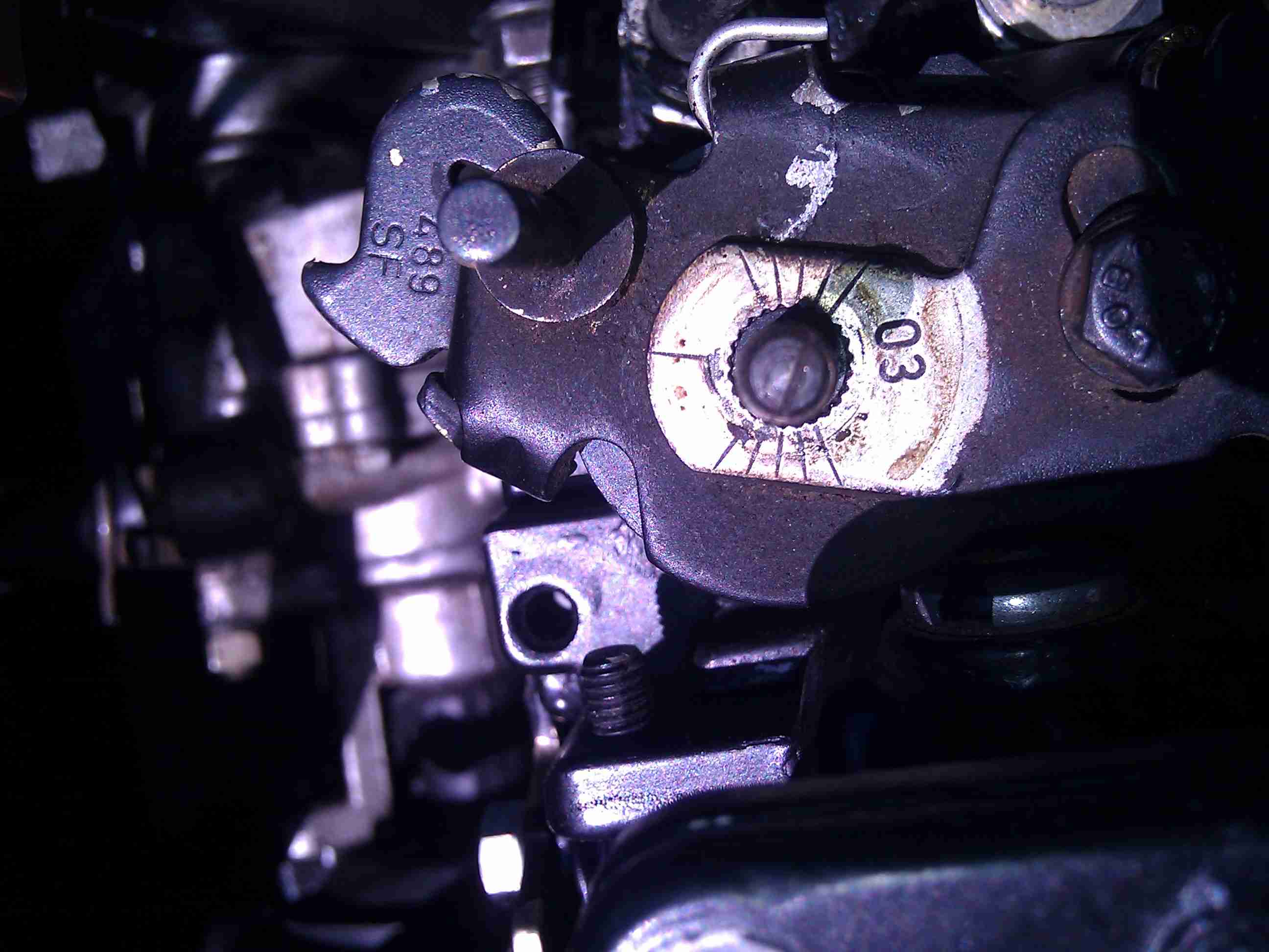
Today I was convinced by 2 pump shops to take the pump out to find what they thought were timing issues causing the gray smoke. It then occurred to me that I could use a mirror to see in the key way slot in the gear. The slot was completely empty. I could see all of the way down it.
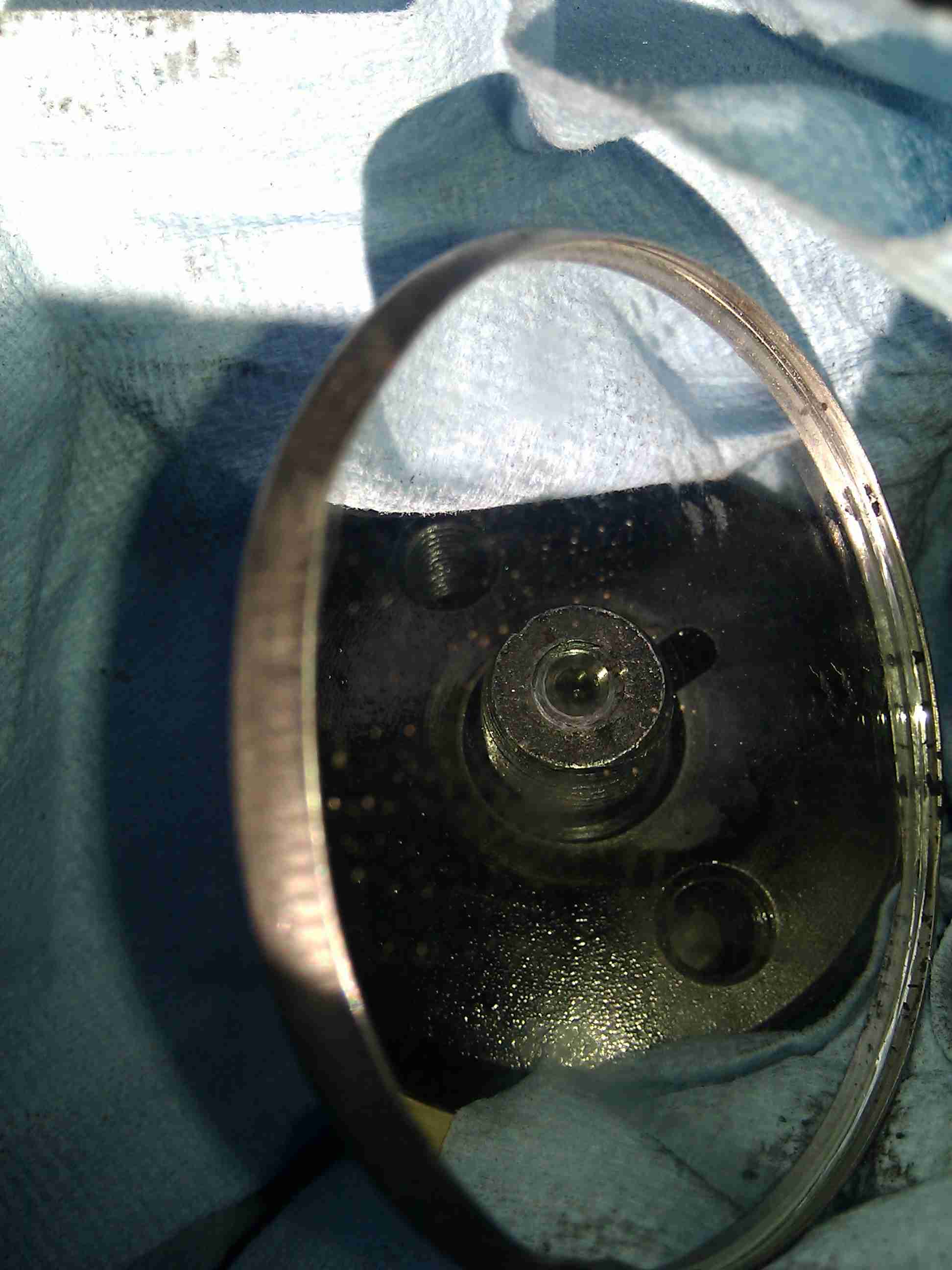
Here it is. A mushroomed key! I must have been close to the slot as a small part of the key was still at full height.
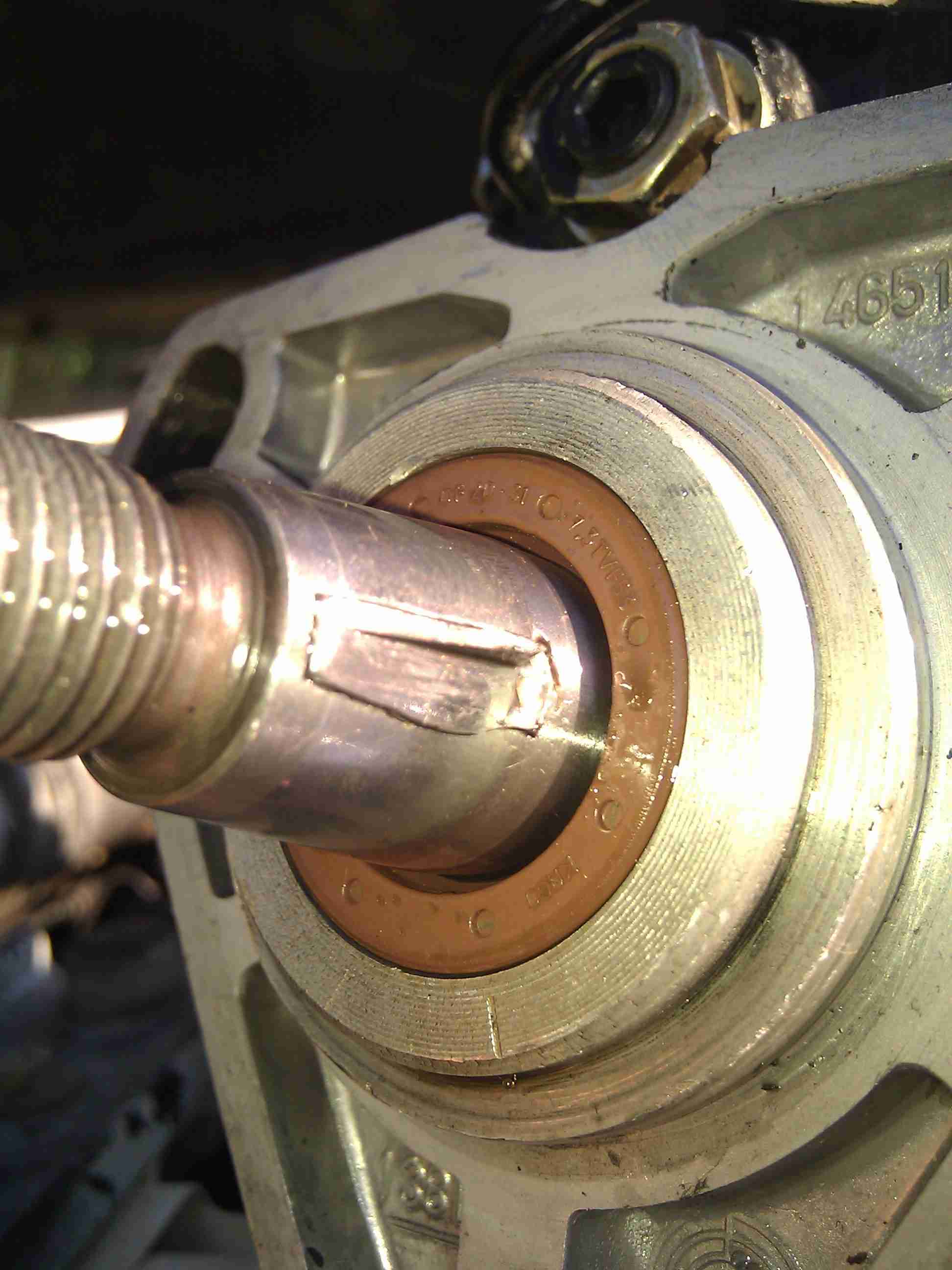
After filing and grinding, I took a punch and hammered the key out again.
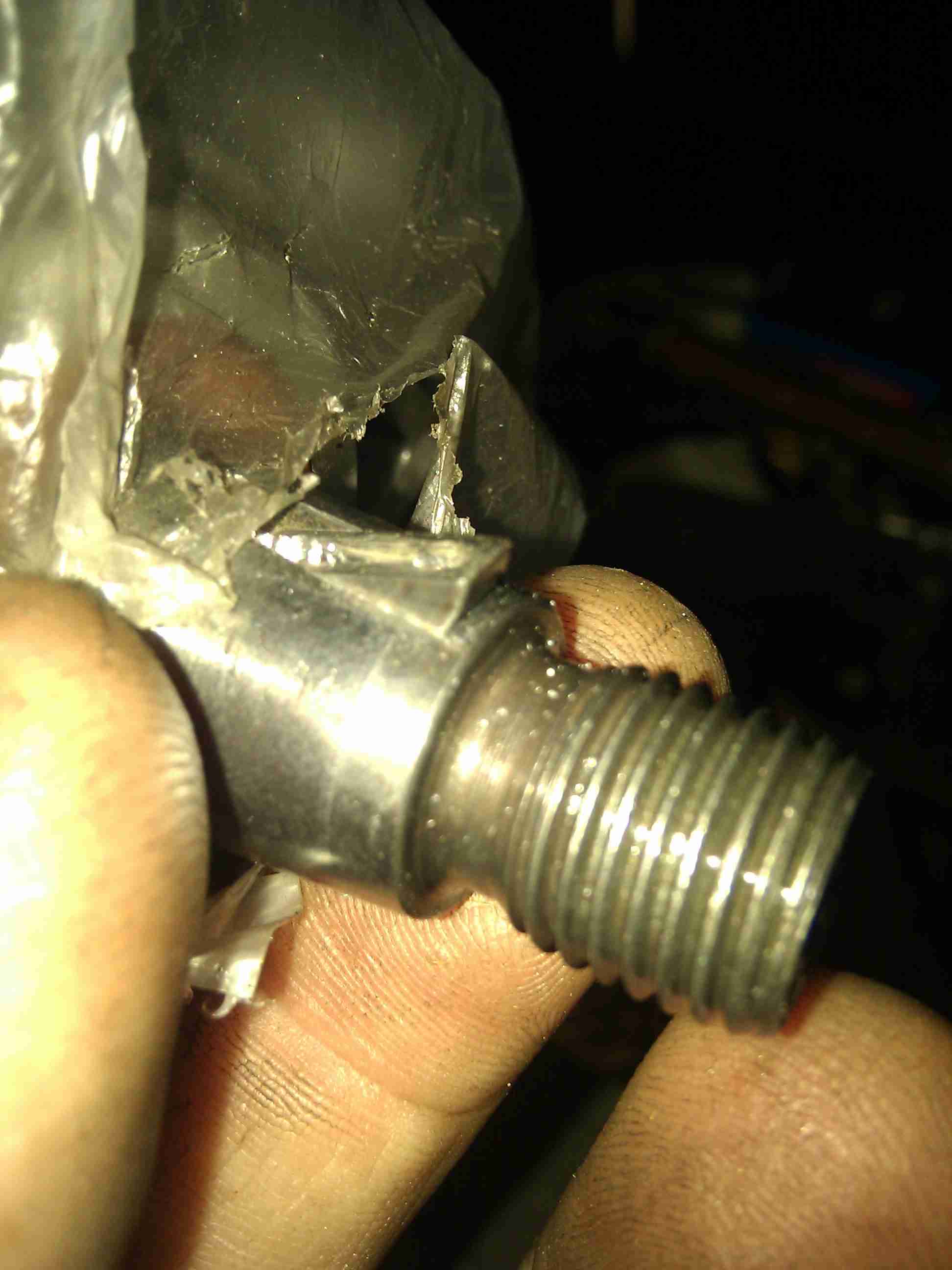
Small diagonal cutters grab keys very well so they can be leveraged out nicely.
I also checked the throttle indexing again. It was fine. It would change the power output more than it would cause gray smoke.
Here is the mark I added to the throttle shaft to help me index it.

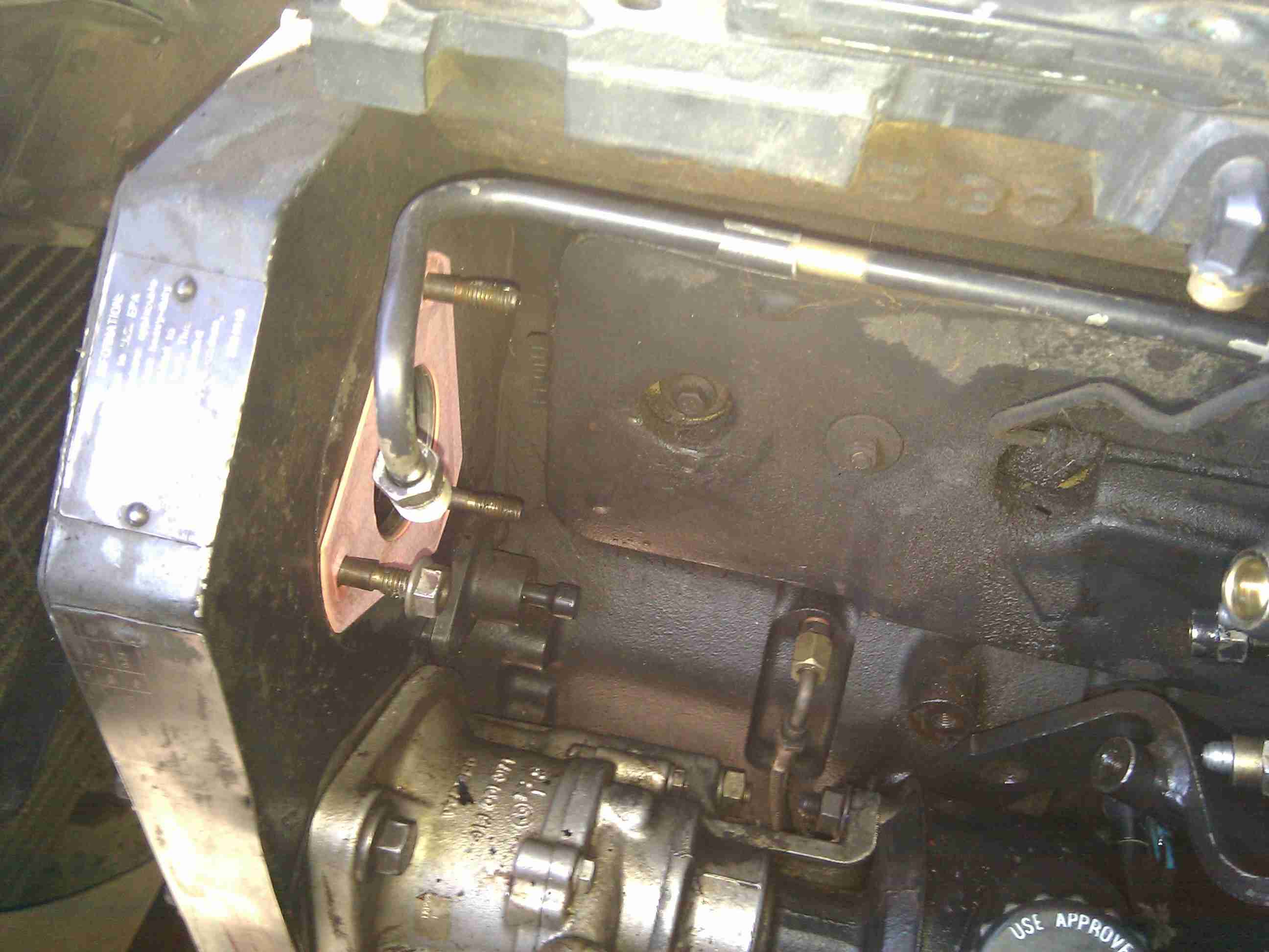
I also found out that I could leave the fuel line in place and still remove the pump easily.
Sun 9 Oct 2011
Drop in all 4 screws. Carefully install the governor spring between the top hat on the governor and the throttle arm as seen here.

As the assembly is brought down to the pump body 2 things have to happen to make them fit together. The collar on the screw at the far left in this pic has to make it to the larger hole for it in the pump body. This is tough because the fuel screw is pushing on the governor arm that has two strong springs on it. It might help a little to back the fuel screw almost all of the way out. It will still push on the governor arm, but it will interfere less. Be careful not to let the collar scratch or gouge the surface of the body. That might cause a leak since that is the surface that the seal sits on.

Once you do get the upper assembly mated to the body, turn the screws in evenly. It’s a little easier to add the throttle arms after all of the screws and distance settings are done.

Set the correct distance that you measured and wrote down for your pump on the fuel limit screw.

Here is how the two bushings and the spring are assembled.

Slide the 2 springs and both bushings onto the throttle shaft. Here is an easier way to wind up the throttle spring while putting the throttle arm over the shaft. I just used an allen key for leverage. Worked very nicely to hold the spring out of the way while the lower throttle arm is installed and correctly indexed!!

Notice how both hooks of the springs are wrapped around the posts. The lower throttle arm is installed.

Here you can see the mark I made on the throttle shaft that lines up with the single index mark on the lower throttle arm. Click on this pic for clarity.
In my hand is the nut and the upper throttle arm. Over the throttle shaft I placed the lock washer and the large rust colored thrust washer. Then the upper throttle arm is added followed by the nut. Tighten the nut, but not too hard. It’s only a 6mm thread.

Add the TPS bracket. Carefully tighten the screws as they are threading into aluminum.

Sun 9 Oct 2011
See on the far right the shape of the shim that was taken out. That will be a reminder that it goes up against the pump body, then the round washer would go next during reassembly.

Lube up the new oring for the governor shaft with STP and install it on the shaft. Install the shaft until it just sticks into the governor area just enough to get both washers back on the shaft. Put them on in the right order.

Reinstall the governor housing onto the governor shaft.

You can see the 4 areas that hold the governor weights.

Look very carefully how the governor is assembled. There is a thrust washer (slightly blue color) that goes on top of the feet of the weights, in a groove on each weight. Then the black sleeve is slid onto the governor shaft. Push the governor shaft in a bit more but don’t allow it to move the black sleeve out so there will be room for the governor linkage.

The governor linkage, twists slightly as you raise it up from below. It’s a snug fit, but will make it. Screw in the two 3 point screws with their aluminum or copper seal washers to hold the governor assembly in place.

Here is the governor in position.

Here is the socket I used for the 3 point bolts. Only 3 of the flats in this socket need to be ground into an arc shape to fit the bolts.

Here I used a 3/8 socket, 1/4″ drive, to slip the o-ring over the threads without tearing it up. Large milk shake or soda straws work well for this too.

Make sure the oring is lubed very well with STP. Screw the governor shaft in with an allen wrench until it bottoms. The pump shop that advised me said to screw the governor shaft out until it’s flush with the face of the pump. Then screw it back in 1.75 turns. That’s what I did. Add the jam nut and torque it down.

« Previous Page — Next Page »