Electrical


While I had the dash apart to fix the masterswitch, I also found the location of an intermittent bulb that was lighting up the 6 and 7 digits on the tack and the left side of the speedometer numerals. Now the bulb lights the dash up perfectly.

Here is where a hidden screw is that allows the dash to be removed.

The cover is rubber. I just prying it out carefully with a tiny screwdriver to reveal the hidden screw. There are only 2 other screws right above the dash gauges to remove. I removed the 3 screws from the bottom of the steering column covers. The bottom column cover pulls down with a bit of wiggling to get it around the ignition switch. Then the 4 10mm nuts that hold the steering column up need to be unscrewed until they are just barely threaded on. This allows the removed of the top steering column cover.

There are only 4 screws holding the dash gauges in, and two electrical connectors on the back side that have to be removed. Here is the back side of the complete dash assembly. This back cover gets removed by very gently prying up of the tabs all around the perimeter.

After the back cover is removed here is the pcb that operates the gauges. There are 2 ribbon cables and 2 pairs of tiny connectors that were carefully removed from their sockets. Then the ribbon flex cable in the lower middle of the pcb gets removed. Ask someone if you don’t know how to properly remove this cable! The tabs of the connector have to be gently lifted up to release the flex cable. Fingers work well here if used gently. Then the tab at the top gets pried up just a little bit to free the pcb. Static discharge into this pcb would ruin it. Put it somewhere safe.

The flex pcb that runs power to all of the light bulbs is show here after the main pcb is removed. The socket with the arrow in this image is the one that was intermittent. The bulb had oxidized leads from a bad connection with the copper in the socket. So I cleaned up the bulbs wires and the socket by scraping them with an Exacto blade. The bulb worked perfectly after this repair. Reassembly is exactly the reverse of disassembly.

The Passenger power window started trying to go up even though it was already fully up. I was told at the 2010 Maker Faire that it was the master switch on the dash that goes bad. Since it’s $180USD for a new one I thought repairing it was a worth while adventure. The first thing I did was to remove the passenger door panel and check to make sure the window motor worked ok. After I verified it worked I put it back together with a better condition door panel and then removed the dash panel. I also had an intermittent bulb lighting up the 6-7 numbers on the tach. So I fixed that while I had the dash out.

Here is the master switch after being removed from the dash. The switch on the right is the passenger switch.

Next the switch level is removed. Gently with a small screwdriver pry this side of the lever off of it’s pivot.

Here is the result. The lever is just barely lifted off of it’s pivot.

Then gently pry the lever off of this side of the pivot, and the lever will be free.

Here is the lever once it is removed. Notice the broken off finger.

Now take the switch apart by gently disengaging the tabs on 3 sides of the switch. The sides of the switch will crack if you pry up very high. Be very careful not to loose the tiny piece of broken plastic finger that is loose inside of the masterswitch or you are screwed! I recommend that you do this disassembly over a table.

Here is the inside of the masterswitch. Notice the tiny broken off piece of clear plastic that use to move the microswitch up and down. It has to be glued back on.

Just simply tack it back on with your favorite brand of superglue. Or as we modelers call it, CA. Let it dry for at least an hour. It’s not instant. Trust me.

The next step is to reinforce the tacked on plastic finger with carbon fiber, kevlar or fiberglass strands using CA to glue to fibers to the plastic on the top and side of the finger. Tweezers really help applying the strands. A microscope won’t hurt any either. I’ve repaired intricate parts like this for years. It works really well.

I also reinforced the other side to keep it from eventually failing as well. Make sure to let the CA cure over night. It’s not instant!! Make sure the opening between the fingers is clear of CA and fiber reinforcement. It has to fit nicely over the switch to actuate it properly.

Carefully push the lever back into it’s position. Get the reinforced finger back to it’s original position toward the outer wall. The other side of the lever has a similar piece of plastic without any fingers that is used to conduct light from an led to the switch lever. Same with the driver’s power window switch.

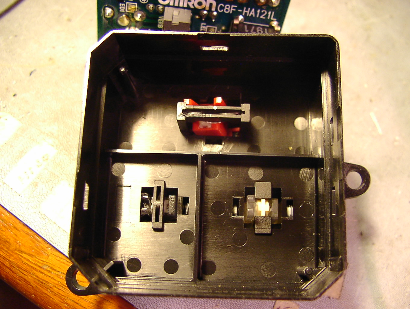
Here is the front view of circuit board. There are 3 switches that have to have to be aligned with the levers in case so they move properly.

Here is the circuit board placed inside of the case. The pins of the various switches have to properly aligned so that the levers can move them. This is with the lever pushed down, showing that the switch is now being moved by the repaired fingers.

This is the lever pushed up showing that the repaired fingers are moving the switch properly.

After careful checking that the switches were aligned with the levers, the master switch was reassembled. It snaps right back together. I could clearly hear the passenger switch clicking as I moved it’s lever up and down. It was not clicking when I started this project, due to the broken off finger.

« Previous Page