[This page was recreated as the orginal is no longer online]
|
|
This page contains the following articles. All the articles will scroll from top to bottom. If you are interested in one particular article, click on the link and it will take you there.
| Emergency Flashers | Ken Chapin | Feb 23, 99 |
| Overhaul of Starter Relay | Chris Olson | Feb 25, 99 |
| Sluggish Starter Motor | Chris Olson | Feb 25, 99 |
| Sluggish Starter Motor | Ken Chapin | Feb 25, 99 |
| Starter Cable Burned | Jerry Pophal | Feb 25, 99 |
| Engine Cutting Out | Ken Chapin | Feb 26, 99 |
| Charging System Diagnostic Procedures | Chris Olson | Mar 21, 99 |
| Dead Starter | Robert Peterson | Apr 08, 99 |
| Build Your Own Digital Voltmeter | J.R. Ferguson | May 02, 99 |
| Starter Bushings | Gordon | May 20, 99 |
| Permanent Magnet Alternator Fundamentals | Dick Taylor | Nov 26, 99 |
| Installing Aftermarket Electrical Accessories | Chris Olson | Dec 03, 99 |
| Download Starter Overhaul Instructions | Ken Chapin | Dec 10, 99 |
| GL1000/1100/1200 Stator Testing Procedures | Ken Chapin | Dec 26, 99 |
1. check the ACG coupler for discoloration, which indicates overheating and it is faulty. This is the connector to the immediate left of the battery and consists of 3 yellow wires. If the connector is found to be discolored and/or brittle from overheating, an ACG Coupler Repair Kit (Part # 31105-ML8-305) is available from your local HONDA dealer. Ensure that the coupler is well packed with dielectric grease. An alternative is to remove the coupler altogether and ?hardwire/solder? the yellow wires together. This method is also acceptable but does make future testing somewhat difficult and would require cutting of the wiring.
2. unplug the ACG coupler and start the engine.
WARNING: Unplugging the ACG coupler while
the engine is running can cause sparks which can ignite flammable fuel
vapors. You could be burned. Do not unplug the ACG coupler
while the engine is running.
3. with a Voltmeter, measure the A.C. voltage between each pair of the three (3) yellow wires in the ACG coupler that leads to the rear of the engine and enters through the rubber grommet leading to the Stator. Conduct the voltage tests between wires A and B, A and C and finally between B and C. With the engine at a steady 3,000 RPM, the voltage should be at least 50 Volts of A.C. voltage from each pair (or phase).
4. if the test indicates 50 Volts A.C. voltage or more from each pair (or phase), the Stator does not require replacement. However, if either pair of wires does show less than 50 Volts of A.C. voltage, replace the Stator.
5. Continuity tests must also be performed to determine if the Stator has developed an electrical short within itself or if it has shorted to ?ground?. With your tester set on the Ohmeter @ R X 1, check for continuity between each pair (or phase) of yellow wires, A and B, A and C and B and C. You should have continuity at all three pairs (or phases). If you find any one pair with no continuity, then this indicates an open circuit in the windings of the Stator and it requires replacement. Then check for continuity between each yellow wire to a source of ?ground?. You should NOT have continuity and if you do find continuity at any wire, this indicates a short within the Stator windings and requires replacement.
** for your Stator to be healthy, it must
pass all of the above tests.
Amp draw of individual circuits:The GL1100 I tested was equipped with accessory clearance/running/tail lighting which draws 3.4 amps and auxiliary driving lights which draw 7.0 amps. It's important to always allow 1.5 amps to keep the battery charged. Even though the GL1000/1100 system will deliver 20 amps, it won't maintain voltage at the regulated level of 14.7 VDC if total electrical load is equal to max charging system output. Normal load on a GL1000/1100 is 12.6 amps; a GL1200 is 13.8 amps. Theoretically this would leave 7.4 amps reserve on the 1000/1100 and 10.2 amp reserve on the 1200. However, these charging systems are rated at 5000 rpm. At slower cruise speeds they put out less than maximum power. The GL1100, for instance, puts out ~17.0 amps at 3800-4200 rpm. That leaves only 4.4 amp reserve. If we turn on the aux running lights (3.4 amps) the charging system is close to maxed out. If we turn on the driving lights, the charging system won't be able to keep the battery charged - and system voltage will start to drop. It' very important to install a voltmeter on your bike to monitor system voltage at all times when running extra electricals. You can safely add electrical load as long as the system voltage remains at ~13.0 VDC or higher. When the system operates at a voltage lower than 13.0 the battery will slowly discharge.
Headlight 5.0 amps (high beam)
Tail and dash lighting 3.8 amps
Ignition system 1.3 amps
Fuel pump 1.2 amps (GL1200 only)
Stereo/audio system 1.0 amp
Battery 1.5 amps
The major differences in these systems is in the regulator/rectifiers as solid state electronics for automotive use was undergoing rapid change during the period these machines were manufactured.
The rectification is what is called a full wave bridge. The windings are connected in a delta configuration, although the diagrams show them as a Y or star, there is no connection to the center of the Y. There are 3 pairs of diodes with each pair connected in series and the 3 pairs are in parallel except for the junction of the anode and cathode of the pairs. The stator wires are connected to the pairs at the junction of their anode and cathode. The common cathodes are connected to the battery positive terminal while the common anodes are connected to ground and eventually to battery negative. This configuration results in 6 pulses per alternator revolution, with each phase being positive (or more positive than the others) for 60 degrees.
How it works: There is a device that senses the battery voltage, and compares it to a reference voltage. If the battery voltage is higher than it should be the sensing device turns on a Silicon Controlled Rectifier which shorts one (or more) of the phases to ground. The SCR is connected to the stator lead(s) at the Yellow wires. The path of conduction is from the stator lead connected to the anode of the SCR to ground, then through either or both of the anodes of the diodes which are not connected to the SCR and then back to the other two phases. This short circuit lasts at most 1/3 of an alternator revolution since the phase changes polarity from positive to negative and the SCR stops conducting. This short circuit has two effects;
1. The output voltage is reduced during the time the short is present and the battery has to supply current during that portion of the cycle.
2. There is at least 60 degrees of SCR conduction during the time the other phases are supplying current thus the current through the shorted phase acts to reduce the strength of the magnetic field and therefore the voltage output of the other two phases.
The power dissipated at this time is less than would be supplied to the operating system at full voltage. While the SCR and diodes have some power loss the voltage drop across the resistance of the stator is limited to the same voltage that would be across 1 diode and 1 SCR - about 2 volts total. Without knowing the resistance of the stator windings there is no way to get a number for the power loss during this time but suspect it is relatively low.
The earliest models used a single SCR across only one of the phases. The voltage reference was a large zener diode connected to the battery through some large resistors. This zener diode in no way shunted any of the power or acted as a control device - it was simply a measurement device. It did get hot, as did the resistors in series with it, and required a good deal of cooling which is why the large heat sink attached to it. It is no doubt this scheme appeared to be the regulating circuit but it was just a very inefficient measurement device.
I don't know when or, even if, the 1100's went to a 3 SCR regulating system (editor's note: they did in 1983) but the 1200's all had a more efficient regulating device and used an SCR for each phase. The circuits in the 1200's are thick film and ceramic substrates with some integrated circuits to do the sensing rather than the discrete components of the '70's. This was about the stage of development of automotive electronics at that time. They required less power, the reference voltage was no longer a big honking zener, and things generally ran cooler.
How the system works in operation:
If the battery voltage is not at the regulated level and the rpm's
are constant you will see an increase
in stator current flow with added load but a drop in voltage.
However your measurement devices may not be sensitive enough to detect
this.
Editors note: I have tested the system on a GL1100 with
a Fluke digital AC ammeter on the stator legs. Setting the ammeter
to the 0-200 amp scale, engine operating at 2000 rpm, cooling fan off,
and no additional load other than stock, the ammeter will indicate ~10.7
amps of current flow per leg. With fully charged battery, turn on
the cooling fan and current flow increases to 11.0 amps. Switch on
aux lighting; the flow increases to 11.2 amps. Switch on aux driving
lights and it increases to 11.3 amps. Obviously, at 2000 rpm the
stator is not able to generate enough power to supply the full electrical
load. Increase engine rpm to 4000-5000 and stator current flow increases
to 12.8 amps.
If the battery voltage is at the regulated level you will see either
an increase or decrease in current and a decrease in voltage with added
load. Well that didn't tell us much did it? Here's why - during
the unregulated portion (when the voltage is not at the regulated level)
the SCR is not conducting and the current in the stator is essentially
AC. During the regulated portion, the SCR is conducting
at least part of the time and some of the current in the stator is
now pulsating DC.
This might give some indication of the reaction of the current probe to the DC. Try to find an RPM at which the SCR isn't conducing - this should be just below the regulation voltage - then slowly increase rpm and observe the ammeter.
As an observation, most automotive electrical systems fail due to heat, heat, and vibration. Hard wiring of the three wire stator connector should have little if any effect on the heat generated by the alternator. Even though the alternator voltage rises to compensate for the added resistance of the connector the power dissipation of the alternator would not necessarily increase if the current out of it did not increase. The power dissipation of the alternator is determined by the current supplied by the alternator and the internal resistance of the stator, not the terminal voltage.
Additional load up to the limits of the alternator will not usually
cause a failure unless the alternator is faulty. By adding loads
such that it is difficult to maintain the battery properly charged, the
risk of alternator failure will increase since more current is being required
and more heat generated within the alternator.
The size of this unit requires a cut-out of 1.31 X 2.68 inches.
I know that there may be some of you who wish they had one of these, but you have NO desire to build it. If you send me e-mail to that effect, I think that I could build one for you. We'll talk. Contact me at jrferg@airmail.net.
SUPPLIES:
(1) Digital Voltmeter/Ammeter Module -- Radio Shack Part # RSU
11461498 (order only from catalog).
(1) 7805 5 Volt Regulator -- This steps the 12 v from the battery to
power the unit and backlight.
(1) Roll or tube of solder -- Best to use a very fine or thin solder
for the linksand CN2 connections.
(1) Roll of wire -- a light gauge will do as the unit pulls a very
small load. I used 3 colors.
(1) 1 Megohm Resistor -- Make sure it is 1% tolorance. This is Resistor
R(a).
(1) 10 Kilohm Resistor -- Make sure it is 1% tolorance. This is Resistor
R(b).
(1) 4 inches of ribbon cable with a 14 pin "head" connector (female).
(1) A "pencil" soldering iron -- should have a fine tip. My iron is
14 watts.
(1) Digital Multi-Tester -- This is for calibrating and for checking
connections and continuity.
(1) Small "Project Board". This is a perforated board that lets you
place and solder parts. Mine is 1 1/2 inch square.
NOTE: R/S normally doesn't carry the 1% resistors. You can order them, though, at the same time you order the unit. Your best bet is an electronics suppy store for these items (except the unit). Check the Yellow Pages.
Let's Build The Thing:
Step 1 --- Assemble ribbon cable to head connector. Insert into Connector CN1.
Step 2 --- You need to close Links 1,2,3,4, and 6. Do this by putting a dab of solder across each link.
Step 3 --- Connector CN1 pins 2 and 4 are connected to ground 12v (-). Also, connect the ground (or common) pin on the 5v regulator to this ground.
Step 4 -- Now, connect 12v (+) to the Vin (Voltage In) pin of the 5 volt regulator AND one end (doesn't matter which) of R(a). Remember R(a) is the 1 M Resistor.
Step 5 -- The other end of R(a) is connected to one end of R(b) (the 10K resistor) AND Connector CN1 pin 1 wire on ribbon cable.
Step 6 --- The other side of R (b) is connected to the ribbon cable wire for CN1 pin 2.
Step 7 --- Connect the Vout pin on the 5 v regulator to the wire from CN1 pin 3. Connect CN1 pin3 to CN1 pin 6".
Step 8 --- Finally, connect the wires fron CN1 pin 10 to the wires from pins 12 & 14. Connect CN1 pin 9 to pin 13.
That's it for the wiring. Now we have to do just a little more soldering.
Locate the annunciator pads on the left hand side. Refer to the instructions. This is what symbol will be shown on the display. We want the "V" for Volts.We want to put a dot of solder across the "V" pad and the "selected" pad. We then want to solder all the other annunciator pads to an adjacent "not selected" pad. Take a look at page three of the instructions to see the example of how they did the soldering for "C".
Congratulations...you've done it! All we have to do now is to calibrate the unit. Because of the resistors we used, the readings are not perfectly linear. We need to calibrate it for the range that we expect to use.
Decide where you want to hook into you power. I found that to get the best readings, you need to hook into the battery itself. Other places have a voltage drop of up to .5 volts. I installed a relay. They are easy to install...all you do there is follow the instructions with the relay. Nonetheless, you now need to hook the + wire from our module to the + terminal of the battery and the - to the - terminal. Also, hook up the muti-tester set to measure 20v. Locate "VR1" (refer to the instructions). This can be turned with a small screwdriver. Slowly adjust VR1 until you get the same reading on both voltmeters. You won't actually get the same reading, but you will get pretty close.
Now you can either make a cut-out in your dash or panel of your choice or do what I did. I used a "project" box that was about the right size and made a cut-out on the top with the screws. I made sure that it was waterproofed with clear caulk and mounted the "box" part under the pocket cover. I also drilled holes to allow air circulation and to prevent accumulation of condensation.
That about does it. I've included a photograph
[http://www.dallas.net/~jsides/dvm.jpg] of the finished and installed unit as it looks on my bike. I've also included
a wiring diagram [http://www.dallas.net/~jsides/vmeter.jpg]
to give you an idea of how it all ties together. If you have any questions
or if I haven't been very clear on something, just send me an e-mail with
your questions. I can be reached at jrferg@airmail.net.
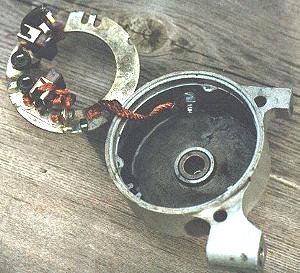 between dissimilar metals and good contact can suffer. The modification
involves drilling a hole in the end cap and securing a separate length
of spiral stranded copper wire with a nut & bolt to a solid connection
of the brush mounting plate (either spot weld, rivet or nut & bolt).
A spot weld is recommended. With this modification, you will notice
an improvement in the cranking performance of your starter. Interested
parties can E-mail Ken -- kenjo@telus.net
or Larry -- las@reach.net.
between dissimilar metals and good contact can suffer. The modification
involves drilling a hole in the end cap and securing a separate length
of spiral stranded copper wire with a nut & bolt to a solid connection
of the brush mounting plate (either spot weld, rivet or nut & bolt).
A spot weld is recommended. With this modification, you will notice
an improvement in the cranking performance of your starter. Interested
parties can E-mail Ken -- kenjo@telus.net
or Larry -- las@reach.net.