Mon 19 Dec 2011
I checked the current draw of the truck’s system with my clamp meter around both ground cables. There were like 8 wires on the positive terminal so that was not going to fit. I saw current draw of 140-150 amps!! It’s only a 120 amp alternator!! I didn’t have my schematics with me so I took my ohm meter and probed about to see how the large grid relays were wired. Both hots went straight to the positive battery terminal. It was a bit rigged by the previous owner. So I disconnected both large grid heater leads. The current draw was now between 35-50 amps now. Sweet!!
Here is a Ford type relay mounted between the grid relays and the battery. It looks after market and rigged at that. A couple of it’s wires went to the positive terminal bolt too.

Here are all of the wires stuck onto the positive terminal bolt! The 2 black leads are the fusible links for the 2 grid heaters. The other 2 leads are from the after market looking Ford relay.

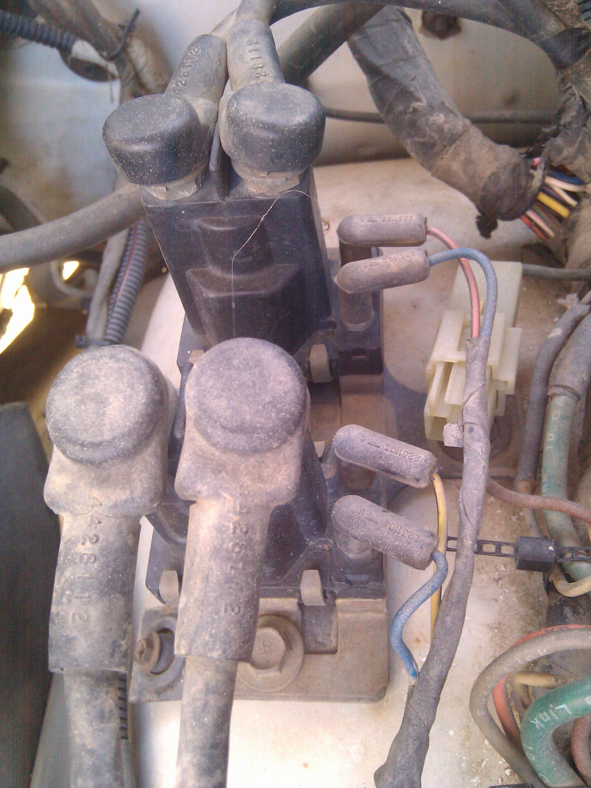
Here are the grid relays. One for each of the 2 grid heaters. The main posts were not shorted together as I checked with an ohm meter. Still need to look at more things to see why the current is dropping the alternator voltage down so low.

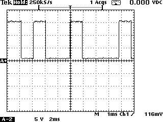
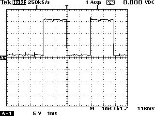
So now I wanted to see how the field terminal looked on a scope. These pics below are the 2 scope shots I took looking at the upper field terminal while charging. Sure enough there are waveforms present!! It shows the pcm has proper output. I could not get a sync on the waveforms, but at least I got good enough shots to show what a proper pcm output is suppose to look like. The crispness of the waveforms told me the pcm field control was working fine.

